Introduction to PID
8059 Blank. beginners' guide to PID for VEX Robotics
Updated on 2021/01/11
Overview
A PID stands for a Proportional, Integral, Derivative (PID) loop. If you’re in middle school/lower secondary, you probably only understand the word “Proportional”, but it’s ok, you don’t really have to know it.
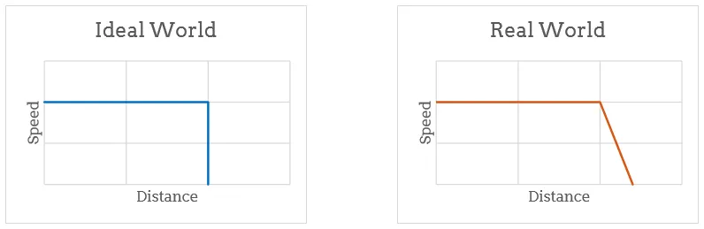
A PID loop is a feedback loop - it takes input from a sensor, processes it and produces an output. In our case, the sensors would be encoders, and the output would be the power of the motor (-127 to 127). In an ideal world, we could tell the robot to move until it reaches a set distance (setpoint), followed by a stop and it would end up at the position we want it to. However, in our world, we have something called inertia. Inertia would cause the robot to exceed this setpoint. To solve this, we would have to slow down towards the end.
Each component, P, I and D are each multiplied by constants, kP, kI and kD, respectively in order to produce the best output and then added together. These constants are usually found based on manual tuning. Although there are many other ways to calculate them, they often do not really work for robots.
Also, I’m going to say this straight up, that I, personally, am inexperienced in the Integral (I) controller. Many of my seniors have tried a full PID controller to no avail. For robot positional movement, I typically use a PD controller.
Counter-argument: Motor braking
Many of my juniors always ask me, “Why don’t we just use a motor brake? You know, power the motor in the opposite direction to stop it?”. To that, I say that it would definitely cause the motor to brake break down. I mean think about it, if I asked you to sprint back and forth between two points, you would definitely get tired really easily. Same with motors. Immediately changing directions for a motor can cause it to wear out. This results in not only more effort to change motors, but also a degradation of performance over time and wasting even more of your club’s precious funding.
Proportional (P) Controller
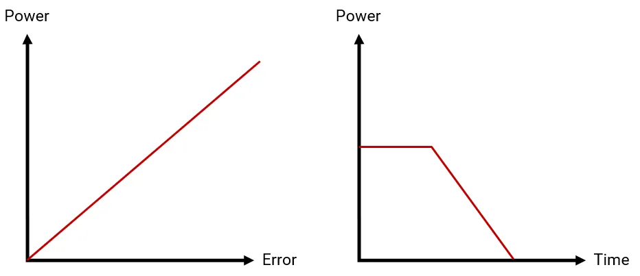
So now that we’ve concluded that slowing down is probably the best option, we need to find out how we are going to slow down. The proportional controller would take care of this. It is simply kP*error. The error refers to the distance between the setpoint and our current position. This would form the bulk of our power. If the error is large, the power output would be high. When the errors reduces, the power delivered to the motor reduces as well.
Simple, right? Don’t forget that we still have to tune kP. Tuning kP for the P controller is relatively easy. Start with kP = kI = kD = 0.0, increase kP by 0.1 (Or small increments, depending on your system) until the robot can reach the setpoint. You may want to verify this by printing the encoder value or displaying it somewhere. If the robot starts braking (denoted by sharp “clicks”) or moving backwards, kP is too high - reduce it. If you are to choose between a higher or lower kP, I suggest going for a higher one as the D controller can regulate the speed for you later on.
Integral (I) Controller
Note that I am not particularly experienced in using the I controller on VEX Robots
The I controller is meant for systems that run for a long period of time. For example, the lifts in a shopping mall. Ever encountered a situation where the lift appears to stall and stops before reaching your target floor? But instead, the lift slowly increases speed again after awhile. This is the I controller. It increases power as time progresses.
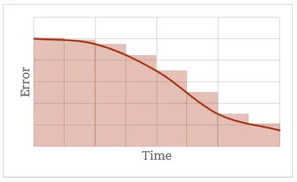
The I component in a PID loop is kI*sum of (errors*dT). For those who know integration, you would be wondering how it is linked. If we were to have the time between loops as dT, the area under the error-time graph (integral of the graph) at each point can be estimated by dT * error. Hence, our area under graph is the sum of errors. Some people prefer to remove dT from the equation and assume a constant sample rate, which works too - at least it does theoretically.
As said before, I am not familiar with the I controller. So here is a simple example taken from George Gillard’s Introduction to PID:
Consider a case where our error is decreasing at a nice constant rate (not realistic), ignoring dT. The following table describes how the integral would be calculated:
| Cycle No. | Error | Integral |
|---|---|---|
| 1 | 1000 | 1000 |
| 2 | 800 | 1800 |
| 3 | 600 | 2400 |
| 4 | 400 | 2800 |
| 5 | 200 | 3000 |
Now, consider what would happen if we had some external influence that caused our error to reduce more slowly (robot moves faster). In the above example it decreased 200 units per cycle. The next table considers what would happen if that was 100:
| Cycle No. | Error | Integral |
|---|---|---|
| 1 | 1000 | 1000 |
| 2 | 900 | 1900 |
| 3 | 800 | 2700 |
| 4 | 700 | 3400 |
| 5 | 600 | 4000 |
As we can see, in the first example our integral was 3000 after 5 cycles. Now, with a slower deceleration, it’s 4000. This increase in value is our indicator of some external influence - an increase in the integral value. An increase in this integral also increases the I component. This helps to boost the motor’s power a little more, similar to the lift example I gave.
Tuning wise, all I can say is that you should keep this value very small if you intend to use it on a VEX robot. Personally, one should try it on a lift though I’ve found that using a PD loop is usually sufficient.
Do note that in the later part of this section in his paper, George Gillard advises that when error <= 0 (Reaches or surpasses setpoint), integral should be set to 0. The integral should also be limited to a maximum value so as not to affect the P controller too much.
Derivative (D) Controller
Alright, this is my favourite one, though many claim it sucks. The main issue with it is that it’s very sensitive (too responsive) and can result in very sharp decreases in power but I’ve got a trick to handle that later.
The D controller will basically act as a dampener. Mathematically, the derivative is the gradient at the point of the curve - in this case, the change in error/dT. Once again, you can remove dT, but I prefer to keep it there just in case of other tasks interfering with the time between loops (the VEX Brain’s processor is not multithreaded and could thus result in inconsistencies). So your D controller would be kD*(change in error/dT).
This can be thought of logically. Your change is error is negative because you are getting closer to a target. If your change in error is big, the magnitude of D would be big, slowing down the system. If your change is error is too small, the system will be slowed down by a larger amount. Either way, there’s sort of negative progress, which is why I mentioned to choose a higher P value.
Now, to tune kD. Increase kD by small increments (similar to small increments in P) until the robot reaches the setpoint consistently, without braking. If the robot tends to stop/slow down significantly halfway then continue, decrease kD.
Juggling PD Controllers
Now we got our entire PID function: power = kP*error+kI*sumError+kD*deltaError. I’ll only be covering PD so it’s power = kP*error+kD*deltaError. After adding in D, we could increase P a little more if it no longer reaches the target. Basically, P should be thought of as the “speed control” while D is the dampener to slow it down significantly more towards the end.
If you can’t visualize this, here’s a pretty good video to show you the effects of each constant:
Some Useful Advice
Remember the problem of D where it may be a bit too responsive and slow down your robot suddenly? Maybe you don’t because you haven’t tried it. But there is a very simple fix. Use another task to limit the change in power of a motor. I will leave this for you to think through, but it does allow you to treat D as purely something to slow down towards the end and would increase your performance significantly.
Also, pro tip for VEX Robotics Competition autonomous routines- tune PD constants for each movement. It is definitely more work, but tuning a PD constant for each movement does not affect other movements. Besides, sometimes you want the behaviour of movements to vary.
Most importantly, trust me on this, tuning this new thing is going to be hard, no doubt. Try to learn as much as possible, observe how it affects the movement of the robot with every change and with experience, you would soon be an honorary PID tuner. You can ask the rest of your team to learn this too! In my team, each member would give their input on how we should adjust our PID constants.
What’s Next?
If you’d like to read another guide, please do read George Gillard’s introduction to PID in the resources section below. It’s really good for beginners.
Now that we know PID is great and all, what if instead of encoder counts we converted everything to inches? That would make programming faster, wouldn’t it? Just use the basic circumference of a circle formula. We can further make this more accurate using empirical testing.
Want to take it one step further? Let’s use odometry - treating the whole field as a cartesian plane (a graph paper essentially). You can read my guide on odometry.
Resources
- Images and Learning from George Gillard’s Introduction to PID
- Basic Concept of PID taken from Team 5757
- [Hardware Demonstration of PID] https://www.youtube.com/watch?v=fusr9eTceEo